Introduction to Control System | Application of Control System | Open Loop and Closed System | Types of Feedback systems
Control System
What is Control System?
The control system is responsible for the behavioural response of any system with input and output ports. It deals with the response of any system with input conditions and corresponding output.
There are 2 types of systems:
Continuous System (represented in s-plane and in Laplace form)
Discrete System (represented in z-plane and in Z-transform)
The input I(s) means continuous input signal and O(s) means continuous output signals to the system represented as H(s). The transfer function means the ratio of output to input in any domain. The transfer function equation
H(s) = O(s)/I(s)
This equation is for continuous form of system when the initial condition is 0. There are 2 types of loop system, i.e., a) open loop, b) closed loop system. The above H(s) system is an open loop system as it does not have any output connected to input. In the closed loop system, the input of the system is added with the output of the system. This is also called a feedback system. The closed loop feedback system is very much responsible for the stability of any system and noise immunity (in Fig 2 shown).
If the system is discrete time it is represented in Z-transform form. It is also possible for us to convert the continuous system to a discrete system using sampling in real life scenarios. The samples are taken per unit time and plotted against the graph to get the discrete-response.
Types of Feedback System
There are 2 types of feedback systems that have been used practically in many applications. They are:
Positive feedback system
Negative feedback system
Positive feedback system
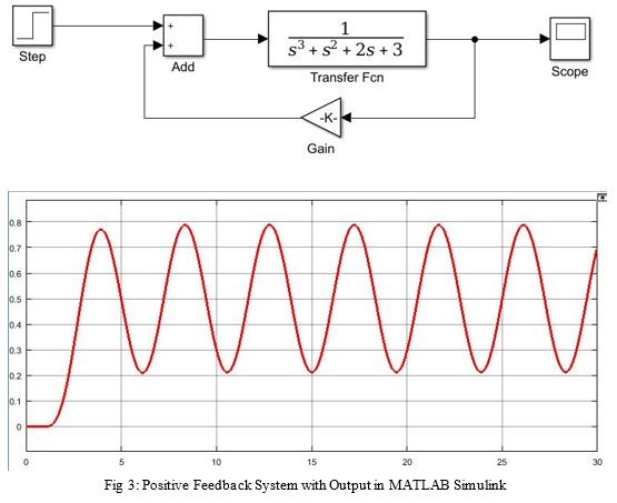
The positive feedback system adds the output with some gain to input of the system creating heavy oscillations. It is generally used as a source for sine wave or pulse generation. This system is very unstable creating uncontrolled noise. Fig 3 shows oscillations at the scope of the system with given transfer function in continuous form. We can get the same type of oscillations in a discrete system.
The major applications of the positive feedback systems are:
Oscillators
Clock circuits
Waveform generation circuits
Wireless communication system
Negative Feedback System
The negative feedback system is exact opposite of the positive feedback system. The output of the system is subtracted from the input of the system and then again fed to input to system as shown Fig 2. The response of that system in scope is shown below.
These systems are very stable, adaptable, controllable, efficient and versatile in their nature. Due it’s adaptability, these systems find their place in various places in electrical-electronics, and mechanical domains. The damping controllability of these systems makes these systems more versatile in their nature.
Applications of Negative Feedback System:
Amplifiers
Robotic Mechanisms
Stable Control Systems
Industrial Control boxes
PLC SCADA systems etc.
Control System’s example
Let us assume we have a robotic arm controlled by a motor. Now the arm is to be rotated from 0⁰ to 90⁰ with the help of a controller. The motor is operated at 12V with clockwise and anticlockwise rotation based on polarity. The requirements to design this system will be
Microcontroller
Motor
Angle measuring instrument (or Potentiometer mapped so that it gives 1V per degree change)
Motor driver
Controller working algorithm design:
Whenever there is an input to the controller for an angle, it will first determine the current position of the motor and calculate error between current angle and target angle.
error εt=(current ∠)°-(targeted ∠)°
Now to reduce the error, the motor will be rotated proportionally so that error can be reduce to 0.
Again, check for the angle in input vs current angle of motor shaft.
So, according to our algorithm, we tried to design this system with a pure electronics circuit in Simulink. The physical input in brown colour gives a signal to the potentiometer from the user as well as from a rotational motion sensor that gives angle output signal as shown in the figure (Fig 5). All the electronically connected parts are shown in blue colour. The Electronic controller generates the PWM signal according to both the input at port 1 and port 2. The internal polynomial is also set so that to give PWM output with 12V and 0V as Vmax and Vmin. The feedback at port 2 gets a signal from the motor shaft and the controller adjusts the input to drive accordingly.
Conclusion
In this blog, we discussed Control System basics and its major application in the real world. We saw types of systems in continuous domain with feedback and open loop systems. We also discussed the types of feedback systems with applications in the real world. In the end, the robotic arm controls using a motor with feedback through a potentiometer and motion sensor for angle measurement. We will see more in detail with different types of application in the Control System with real world examples and also MATLAB Simulations.
I hope you would like this blog and get some clear idea on control systems and control system theory with it's applications. In my previous blog I explained about PID controller but then I realized about some basic concept that would be needed to understand main working and application of PID controller. I will soon come up with PID controller and how to simulate it in MATLAB tutorials with PID tuning... till then stay tuned to this page...


Great content an presentation.
ReplyDeleteVery insightful!
ReplyDeleteVery informative!!
ReplyDeleteGood explanation!
ReplyDelete