PID Controller in MATLAB/Simulink using Transfer Function approach | PID Controller in MATLAB | How to simulate PID Controller in Simulink
| Source: MathWorks |
| Source: MathWorks |
REVISION
In previous blog, we saw what is control system, what is PID controller and it's basic explanation. I really hope you all are familiar with all these concepts and now we can further go to MATLAB/Simulink application of this controller.
Steps to Simulation
It has always been observed that with low RAM or after internet connection, the MATLAB/Simulink become slow in functioning. The Simulink takes time to open, so using command line to open Simulink would be better.
 |
| Command Line text for MATLAB |
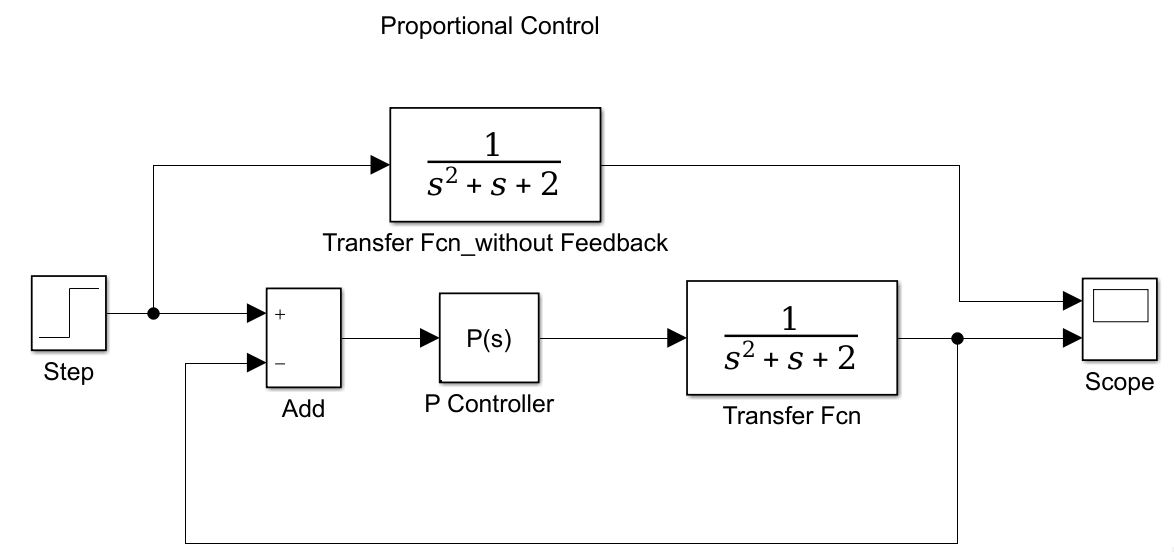
Now open the transfer function block and configure it like this
In this, the array of the numerator coefficients of s², s and constant, must be written and same as for denominator as highlighted. Now open the PID controller block and given this dialogue box will appear.

Select the highlighted configuration parameters. Now click on Tune button as shown in RED circle. This tuning of parameters of Kp, Ki, and Kd and filter coefficient can be obtained. A new dialog box will appear for tuning the PID tuning. The best thing of the Simulink is it automatically recognize the plant model and try to give the best tuning value of these parameters. Since we generally use parallel PID controller in industry. Many people ask what is filter coefficient?
The filter coefficient is used to implement derivative action. Since implementing something like "Kd*s" is not possible since implementing improper transfer function is not possible.
So basically it just limiting coefficient for derivation operation.
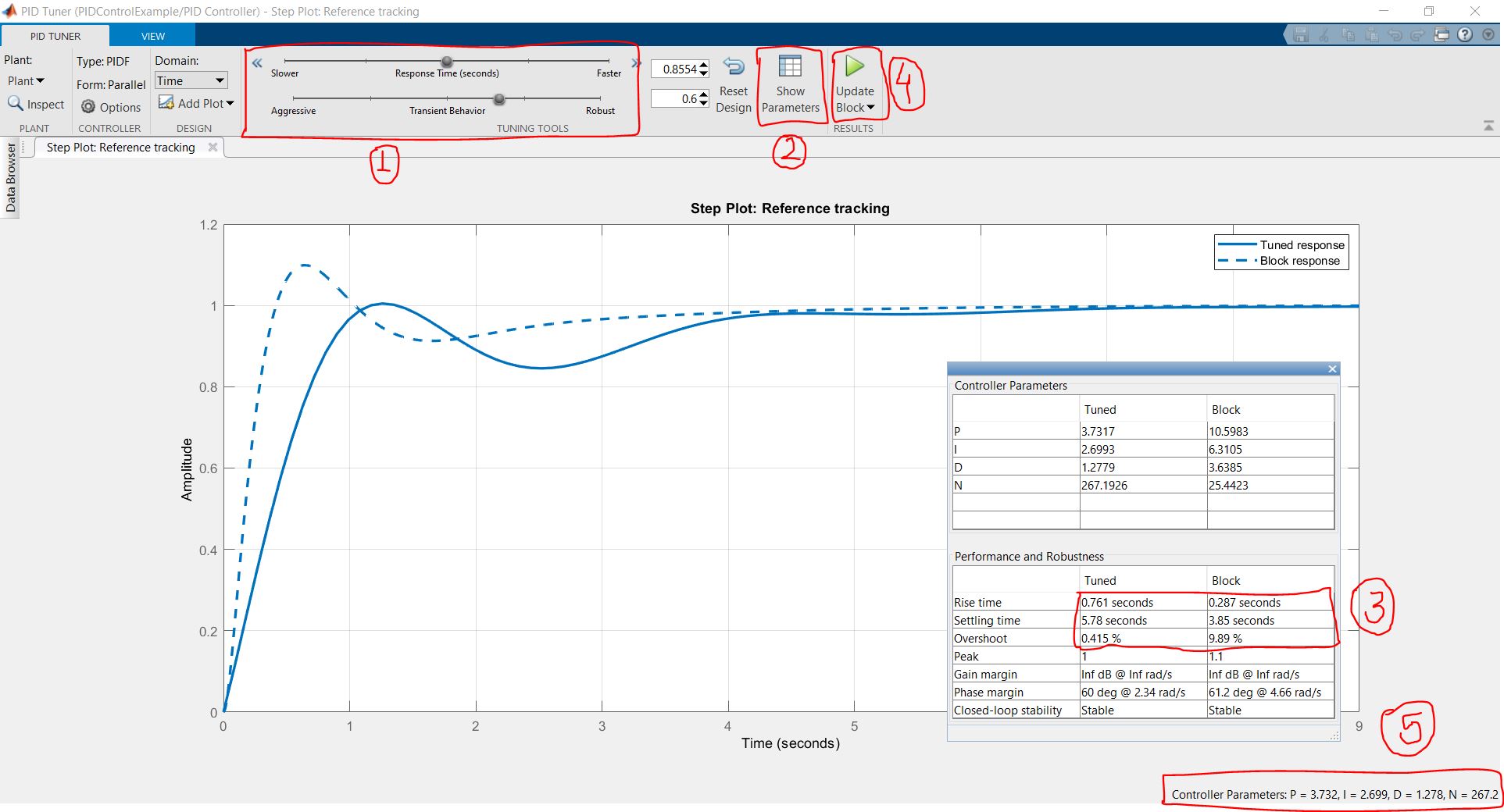 |
| PID Tuner Dialogue box |
- Tuning Tools: This tool is used to make tuned response of the plant as fast or slow, robust or aggressive. As the system becomes fast and aggressive, the overshoot percentage becomes high and not good for step response of the plant as it may be dangerous. Slow and robust system have accuracy but slow response is not accepted in many systems as it may lead to wastage of material and energy.
- Show parameters: This option gives the comparative data of step response of the block before tuning and after tuning, with P, I , D and N value as shown in this figure. In general, following parameters must be maintained.
- Peak Overshoot: < 10% - 12%
- Settling Time: 2 sec - 5 sec
- Rise Time: < 2 sec
- Closed loop system must be stable and no oscillations
- Parameters: These are some important parameters that must be controlled as per above units.
- Update block: Now, after controlling all these parameters and tuned response, all values will be updated using this button.
 |
| PID scope output |
 |
| PID controller comparison |
 |
| PID Scope Output |
Bonus Simulations:
Major of the people ask about ideal PID vs parallel PID controller and it is sometimes very problematic to have comparative study of both. For that I created a simulation for the purpose.
 |
| Ideal PID controller |
 |
| Parallel PID controller |
 |
| Comparison between both types of controllers |
Summary
Message from me
Hello folks...!!! I pray this pandemic treats you well. First of all I am sorry for posting so late. I hope you must have got the idea how to tune and use PID block in Simulink. In future blogs, I will be covering other approaches for tuning the PID block, like frequency based tuning and transfer function prediction with input-output data as well as state space based plant's controller. Till then please practice this with different stable, unstable, and marginally stable 2nd order transfer function.
Regards
-Curious Silly Yours
😀😀😀


Thank you so much for this crystal clear explanation in very simple language...
ReplyDeleteWaiting for further contents . . :)
Nice explanation and very simple language.
ReplyDeleteThank you so much for such a nice explanation.
ReplyDeleteNice explaination
ReplyDeleteThank you so much for the great explanation with examples and simple language. Waiting forward to your new blogs with good concepts.
ReplyDelete